Building a WebXR version of Doom.
Not keen on the details? Jump straight to the demo at https://doom-webxr.ianbelcher.me
Doom is one of the original truly hackable games. Some of my earliest hacking was on Doom building my own levels and there is still a number of online communities who still do this today, decades after Doom was released.
I’m also a significant fan of VR, and have previously tinkered a little with WebVR, previously capturing my travels for a few years, as well as creating basic Three.js environments which you can see in this example video.
I tried out A-Frame earlier this year and it provides a great abstraction layer around Three.js for building WebVR environments and as of the last few days, it now supports WebXR. While getting A-Frame up and running is pretty quick and easy, the next step of building an interesting environment for an immersive VR experience is a much more involved and complicated problem.
It occurred to me that building out Doom levels might actually be a great candidate for this purpose due to the primitive shapes that you have control over within A-Frame, unless of course you want to start getting involved with 3D models.
The results actually turned out to be better than I was expecting given the sparse amount of time I’ve had to work on this project during the year. You can try out the demo at https://doom-webxr.ianbelcher.me and the source code is at http://github.com/ianbelcher/doom-webxr.
While the WebXR Device API has a working draft standard it is still very early days with browser support for WebXR basically being introduced in Chrome 79 earlier this month (Dec 2019) and A-Frame releasing their first major semantic version just yesterday.
The following gives an idea for what the first level looks like when using Vive on Windows with Firefox as the browser.
Safari on mobile also works well as long as you enable motion controls after the first interaction.
If you want a reminder of what the original game was like, you can play the ultimate version of Doom here.
The following is a bit of a run down as to how I managed to get this put together. There are still a number of bugs to fix to get everything perfect, but as you can see from the video, it’s all pretty close.
Overview of data
Using the package @nrkn/wad I managed to extract the required data from the WAD (where’s all the
data) file. WAD files are what Doom uses to store everything from map data, textures and sprites,
as well as sounds and anything else the game requires. It’s somewhat a combination of tar
(concatenation of files into a single file) and netCDF (single file, self describing structured
database).
The following is an overview of the main data types that are available within the WAD file that I’m interested in.
vertexes
vertexes are 2D points which all other map artifacts reference. While this data is returned as an
object with x and y coordinates, it’s better to think of these points as x and z. Within 3D
space, these points are similar to seeing points laid out over the surface of the VR environment
or ground. I want to keep the y axis as the ‘physical’ up and down in 3D space to save confusion
later on.
[
  {
    "x": 1088,
    "y": -3680
  },
  {
    "x": 1024,
    "y": -3680
  },
  {
    "x": 1024,
    "y": -3648
  },
  {
    "x": 1088,
    "y": -3648
  },
  {
    "x": 1152,
    "y": -3648
  }
]
This is the first 5 vertexes in E1M1. Pretty simple stuff so far.
linedefs
linedefs basically make up the map in xz space by joining vertexes objects. These objects
determine the behavior of walls within a Doom level (as can be seen by the flags property), and
also reference sidedefs types and sectors objects.
[
  {
    "startVertex": 0,
    "endVertex": 1,
    "flags": {
      "impassable": true,
      "blockMonster": false,
      "doubleSided": false,
      "upperUnpegged": false,
      "lowerUnpegged": false,
      "secret": false,
      "blockSound": false,
      "hidden": false,
      "shown": false
    },
    "specialType": 0,
    "sectorTag": 0,
    "rightSidedef": 0,
    "leftSidedef": -1
  },
  {
    "startVertex": 1,
    "endVertex": 2,
    "flags": {
      "impassable": true,
      "blockMonster": false,
      "doubleSided": false,
      "upperUnpegged": false,
      "lowerUnpegged": false,
      "secret": false,
      "blockSound": false,
      "hidden": false,
      "shown": false
    },
    "specialType": 0,
    "sectorTag": 0,
    "rightSidedef": 1,
    "leftSidedef": -1
  },
  {
    "startVertex": 3,
    "endVertex": 0,
    "flags": {
      "impassable": true,
      "blockMonster": false,
      "doubleSided": false,
      "upperUnpegged": false,
      "lowerUnpegged": false,
      "secret": false,
      "blockSound": false,
      "hidden": false,
      "shown": false
    },
    "specialType": 0,
    "sectorTag": 0,
    "rightSidedef": 2,
    "leftSidedef": -1
  }
]
sectors
sectors type objects are made up of a collection of linedefs. These objects are equivalent to
a polygon in xz space.
Each object contains a floor and ceiling height, as well a texture to use for each. They also
include light, type and tag properties which are used for the Doom renderer and might come
in handy later if I decide to play around with lighting and behaviors for sectors based on their
type.
[
  {
    "floorHeight": -80,
    "ceilingHeight": 216,
    "floor": "NUKAGE3",
    "ceiling": "F_SKY1",
    "light": 255,
    "type": 7,
    "tag": 0
  },
  {
    "floorHeight": -56,
    "ceilingHeight": 216,
    "floor": "FLOOR7_1",
    "ceiling": "F_SKY1",
    "light": 255,
    "type": 0,
    "tag": 0
  },
  {
    "floorHeight": 0,
    "ceilingHeight": 0,
    "floor": "FLOOR4_8",
    "ceiling": "CEIL5_1",
    "light": 255,
    "type": 0,
    "tag": 4
  }
]
sidedefs
sidedefs objects give further information relating to each side of linedefs objects. The main
purpose of this type is determining what each part of a wall should look like.
[
  {
    "x": 0,
    "y": 0,
    "upper": "-",
    "lower": "-",
    "middle": "DOOR3",
    "sector": 30
  },
  {
    "x": 0,
    "y": 0,
    "upper": "-",
    "lower": "-",
    "middle": "LITE3",
    "sector": 30
  },
  {
    "x": 0,
    "y": 0,
    "upper": "-",
    "lower": "-",
    "middle": "LITE3",
    "sector": 30
  }
]
These are the first 3 sidedefs objects. You can see that middle property for each is set. This
value is a graphic which is also included in the WAD file.
Middle, upper and lower refer to the different segments of wall, and are related to the heights of
the ceiling and floor of the sectors which are on each side of the sidedefs object.
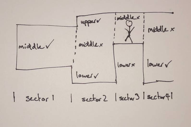
As an example, the following diagram in xy space (with a little added character to make things
easier to understand). There is typically a sector on each side of a sidedefs object, each
with their own floor and ceiling height.
middle refers to the space in the y plane which is greater than both floor heights, and lower
than both ceiling heights of the sectors on each side. In the case there is no sector on the other
side, middle is just the area between the single sectors floor and ceiling height.
In the above diagram, we can see the middle section between sector 1 and sector 2. Typically in a situation like this there will be no graphic supplied, as to the player, there is no wall present. The middle section for the left most part of sector 1 would typically have a graphic supplied though as there is no sector on the other side.
upper refers to the space in the y plane which is greater than one sectors ceiling height while
also being lower than the other sectors ceiling height.
lower refers to the space in the y plane which is lower than one sectors floor height while
also being higher than the other sectors floor height.
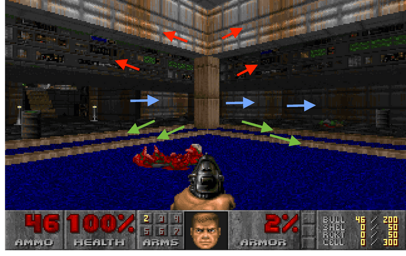
The following screenshot gives an indication to middle (blue arrows), upper (red arrows) and
lower (green arrows) within the game.
things
things are objects that define items within a map. These can be decorative sprites, enemy
starting positions, player starting positions and also include a flag object that defines when
these objects should be used, such as difficulty levels.
[
  {
    "x": 1056,
    "y": -3616,
    "angle": 90,
    "type": 1,
    "flags": {
      "easy": true,
      "medium": true,
      "hard": true,
      "deaf": false,
      "multiplayer": false
    }
  },
  {
    "x": 1008,
    "y": -3600,
    "angle": 90,
    "type": 2,
    "flags": {
      "easy": true,
      "medium": true,
      "hard": true,
      "deaf": false,
      "multiplayer": false
    }
  },
  {
    "x": 1104,
    "y": -3600,
    "angle": 90,
    "type": 3,
    "flags": {
      "easy": true,
      "medium": true,
      "hard": true,
      "deaf": false,
      "multiplayer": false
    }
  }
]
So all up, the data describing a given level is fit for the purpose of the Doom engine, but is set up in a way that doesn’t really afford setting up a 3D environment very easy. Doom levels are in effect 2 dimensional with a pseudo y dimension, for instance, there is no way for a map to have a overlapping sectors of different heights (this was a fundamental difference between Doom and the later released Quake).
Building out the map therefore uses quite a bit of transformation and algorithm design in order to create data that can actually be used.
Building the map
There are 3 separate main concerns that need to be addressed to build the basic map, and there are the floors and ceilings, walls and things (such as enemies, artifacts etc).
Floors and ceilings
Floors and ceilings are the most difficult thing to build. While the polygon for each sector is a simple polygon and it is easy enough to collect all linedefs for a given sector and string them together as a linked list or within an array there is a caveat which makes this process a little more complicated.
There are a good number of cases where a separate sector will exist fully within another sector and in these cases, we need to carve out this interior polygon from the sector that it exists within.
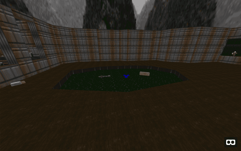
As a visual example in the Episode 1 Mission 1 (E1M1) map, in the outdoor area there the main sector (which is the brown texture). The polygon for this sector traces right around the outside of this courtyard without any reference to the missing section in the center of the courtyard (the green section).
This is obviously handled in the Doom engine fine, but for the purposes of adding polygons to a Three.js scene, we can only create simple convex polygons meaning that we can’t ‘cut holes’ such as is the case in with this interior sector.
To solve this issue, it is possible to remove this sector by cutting out the interior sector much like you would if cutting it out of a flat sheet of paper. The only caveat to this is that to be valid polygon, there must not be any overlapping lines. To do this, the following algorithm is employed.
Step 1: Join up all the linedefs for all the polygons in a level and and ensure that the direction that they are linked in is a clockwise direction. This can be done by adding up the angles of each vertex in the polygon and ensuring that it is a positive sum and reversing the list if not. More information can be found on this great SO answer.
After this is done, all polygons will be clockwise and taking the courtyard example as a visual example again, the polygons will look like the following, indicated in red (These images are using the program Slade which is a great Doom editor, much better than I was using a ‘back in the day’).
Step 2: To find polygons that exist in other polygons, an exclusive point in each polygon must be found and raytraced against all other polygons to see if it is inside the other polygon.
Raytracing can be expensive so doing a quick bounds check of each polygon and comparing these first saves a lot of processing time.
In the case of the courtyard sectors, a bounds check would indicate that there could be one polygon inside the other, so taking an exclusive point on one and raytracing it against the other determines if the sector exists inside the other, indicated in light blue.
Step 3: Once it is known that one sector exists in the other, the best place to ‘cut in’ to the containing sector is found by finding the two vertices in each polygon which are closest, indicated in yellow.
Step 4: This is a pretty big gotcha in this algorithm and the reason why we need everything in a clockwise direction. To avoid overlaps in the resultant polygon, we reverse the interior polygon direction so that it is now counter-clockwise indicated in blue.
Step 5: To cut the interior polygon out, it’s a matter of splitting both polygon chains at the two closest vertices so that each polygon starts and ends at their respective closest vertex, and then simply adding the interior polygon chain to the end (or front, doesn’t matter too much) of the exterior polygon chain effectively giving the following result, a polygon which doesn’t have any crossing lines and can be created within Three.js.
One of the benefits with this algorithm is that the resultant polygon is still clockwise, so in the case there are multiple interior polygons, using the same strategy will remove all of them without having to do any other manipulations. There are cases where this algorithm will fail with multiple interior polygons but for data in the Doom WAD this algorithm appears to work for all cases as far as I can tell so far.
Step 6:
At this point, the polygons for floors and ceiling are known but constructing these in a Three.js scene can be difficult. Polygons in Three.js need to be convex to draw properly, and it’s definitely known that there are concave polygons based on the algorithm just described for removing interior polygons.
For this particular implementation I created a special A-Frame sector component to handle the
polygon data correctly and build out these concave polygons using a combination of
Shape and ExtrudeBufferGeometry in Three.js. ExtrudeBufferGeometry creates the polygon by
building the polygon shape out of only triangles of various sizes and allows the sector polygons
to be drawn correctly.
By adding a class to all floor sector polygons of floor, when setting up the A-Frame scene it’s
a simple case of adding collision-entities: .floor; to any teleport-controls entity allowing
teleporting in VR mode very easily.
Walls
Compared to floors and ceilings, walls are quite easy. As previously discussed, a wall can have
three different sections, that of middle, upper or lower. It’s a pretty simple case of
iterating over all linedefs, determining the floor and ceiling height of the sector on each side
and creating an A-Frame plane entity based on these values.
One of the complexities here is needing to place these planes based on their center point.
Each plane is placed based the midway point of the x, y, and z axis. The width is determined
by the length on the xz plane and height by the difference in heights of each sector on each side
of the linedef depending on the middle, upper or lower values.
With the center point of the plane and it’s height and width, the plane can be drawn, the only
remaining thing to do it rotate it on the y axis so that it faces the correct direction.
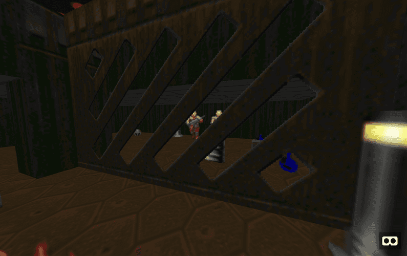
There are a number of smaller rendering considerations with walls, one being the inclusion of
alphaTest: 0.9; on the material allowing for alpha channels in the texture to be transparent,
an example of a such a texture being the grates at the end of E1M1.
Sprites
Adding map artifacts to the scene is comparatively easy. Iterating through each thing in the
data, it’s simply a case of getting the position in the xz space which is already supplied and
finding the height based on sector in which the thing exists in.
Some thing references have multiple sprites due to the fact that they move or are animated. In
this case, I’ve taken the first image and used that. It shouldn’t be too difficult to animate these
sprites though.
Next steps
At this point, it shouldn’t be too difficult to animate sprites which have multiple textures. This should be an easy addition which should add a bit more liveliness to the environment.
It wouldn’t be too difficult to give certain sprites knowledge of the sector that they exist in either which would allow things like the former humans and imps to move around and be animated.
Certain levels can’t be fully explored in VR as they require lifts to work. Would be great to get these sector types to have interactions built in so that lifts work. This could be difficult though. Perhaps all lift sectors could operate on a timer automatically. I’m unsure how the camera system in A-Frame operates in the case that the teleported to entity changes position. Definitely something to try out in future.
And there are still a number of bugs that need fixing. Two main ones is that my polygon algorithm
for linking all polygon sides doesn’t work in the case that a vertex is used more than once (like
a figure 8 sector). The second is the algorithm for finding the sector a thing is in fails if
the location of that entity is on a line between two polygons. Need to investigate this further
but by giving these locations a slight offset if it fails initially should likely work.
Wrap up
If you’re still reading this post, it appears like you’re interested! I’m obviously happy to accept PR’s to the repo if you’ve got any ideas. The current quality of the code leaves a lot to be desired as I’m often highly time constrained with projects like this, but hopefully it’s understandable enough if you want to get involved.
This project has opened a number of opportunities for me to increase my knowledge. I’ve always been interested in spatial styled programming problems and getting my head around the concave polygon issue was a real rewarding challenge in this project.
I’m hoping WebXR is something that grows strongly in the future. The possibilities for using VR and AR in an open online environment presents many possible opportunities and with the introduction of this standard API, we might see a lot more solid attempts to use this technology on the web compared to the relatively weak uptake for WebVR over the last few years.


